Blog 6 (Project Development)
- yanzhen21
- Feb 17, 2023
- 10 min read
Updated: Feb 19, 2023
1. Our Team Chemical Device
Team Chemical Device: Automated CO Monitoring & Ventilation System
Background: Carbon monoxide is produced when incomplete combustion takes place, whether it be during the burning of coal, wood or any other fuel. If carbon monoxide is inhaled, it can lead to several health problems, such as headache, dizziness, weakness, upset stomach, vomiting, chest pain, and even death.
Vietnamese people in the rural areas are dying due to carbon monoxide poisoning. To protect themselves from the cold weather, they burn charcoal in their homes to keep themselves warm. People are unaware of the dangers of carbon monoxide and how it can be produced, so they do not have proper ventilation in their houses.

Problem Statement:
Vietnamese people in rural areas need carbon monoxide detectors and ventilation systems, to prevent CO poisoning from burning coal for warmth in their homes.
Need Statement: How can we reduce the number of people in Vietnam affected by carbon monoxide poisoning?
How our prototype can solve this issue:
When the CO level (in ppm) exceeds the normal level, the user will be alerted and the ventilation system will be activated. This will reduce the chances of people getting carbon monoxide poisoning. The prototype is economical and effective. People will feel safe in their homes when they burn charcoal.
Hand Sketch of Chemical Device:

2. Team Planning, Allocation and Execution
Team members:
Ngo Van Anh - Chief Executive Officer
Lim Yan Zhen - Chief Financial Officer
Jeremy Wong - Chief Operating Officer
Jeevan - Chief Safety Officer
Finalised BOM Table:

Planned Gantt Chart:

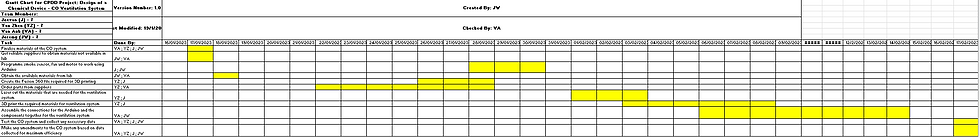
Actual Gantt Chart:
Task Allocation:
Lim Yan Zhen and Jeevan - CAD
Jeremy - Arduino Programming
Van Anh - Assembly of Prototype
3. Design and Build Process
Brainstorming and Building Process:
Right after our mid-semester tests, we started to delegate the tasks for each team member. Prior our last CPDD practical lesson, we gathered together and did fusion 360 for the components we needed. Some parts were the hollow cylinder for the fan and the stand to hold the motor. During the practical lesson, we realised that we needed to have a mechanism to our prototype. Out of all the mechanisms that we learned, we felt that gears is our best bet in succeeding as we were all quite familiar with the mechanics of it. Thus, we started to brainstorm of ways to integrate gears into our prototype. Then, we thought that the suction of fan was insufficient to ventilate out the CO in the "room". Hence, we thought of a gate which opens when the CO level is in the dangerous level by using a mechanism called Rack and Pinion. We started to think of where we could place the mechanism and what were the dimensions. We also needed a motor to turn the gear for the gate to slide open. We decided to use a 360 degree servo which was supplied by the lab. After finalising everything, we all got to work. While 3D printing the other components that we did fusion 360 for, Jeevan and I started on the fusion for the Rack and Pinion. Jeremy and Van Anh were doing the programming for components such as the motor, LED, buzzer and the 360 degree servo. After a while, the fusion for the Rack and Pinion was finished and started to 3D print it.
In the second week, we continued our operation of the our prototype. Prior to that week, we did the sketches of the "room" in fusion 360 and booked a laser cutting session in the library FabLab. While Van Anh and Jeremy continued the programming, Jeevan and I went to laser cut. After obtaining the laser cut pieces, we felt that the length of the pieces were too long, making the room abnormally big. The main components we needed to put into the room were only the Arduino UNO maker and the breadboard. Thus, we resketch on fusion 360 and laser cut again. At the lab where Van Anh and Jeremy was doing the programming, they also encountered an issue. The connecting wires were not long enough. Thus, they decided to solder two wires together by cutting the ends of the wires. This was a new skill we were able to pick up during the operation. When Jeevan and I returned to the lab, we realised that we needed a stand for the servo. In addition, we wondered how we could rotate the pinion on the rack using the servo. There was no connecting parts between them. Thus, Jeevan and I decided to redo the fusion of the pinion. We made a protruding rod at the centre of the pinion. By the end of that day, we were able to have the walls of the room (acrylic sheets) and the finished part of the programming.
In the third week, we came together and tried to finish our prototype. We used acrylic glue to glue our walls of the room together, creating a rectangular box. Then, we used hot glue and double-sided tape to stick our components into their designated area in the room. Occasionally, some components would fall out due to the hot glue cooling too fast, not allowing the components to stick on the smooth acrylic surface. Although we could use the double-sided tape for some parts, however, there are other parts which would need extra mechanical strength to hold them in place such as the holding of the 360 degree servo on the stand. The stand also have to be firmly attached to the acrylic sheet. Thus, the hot glue have to be used. The programming part was also an headache for Jeremy since we had to have 4 different functions to activate simultaneously when the CO level reaches a dangerous level. In addition, the gate which was a free-sliding door moved using Rack and Pinion was very inconsistent. The clearance between the pinion and the rack have to be very precise so that it can move more fluidly. In the end, we "finished" our prototype, however there were still some bits of programming still lacking.
In the last week, we wanted to finalise everything and begin our preparation for the CA2 presentation. In the midst of doing some adjustment to the programming to operate rack and pinion better, we originally had only programmed the buzzer in arduino board as we thought the buzzer that I bought from online was complicated to program. However, when we searched how to program and wire it. It was stupidly easy to do. When we run CO system, the buzzer was able to give off a much louder sound than the one in the arduino board. All in all, although the gate was inconsistent, we were satisfied with our results.
Finalised Sketch of Chemical Device:

When comparing our initial sketch with the finalised sketch, you would notice that they are a lot of changes that we did along the building process. First of all, we definitely could not use rechargeable batteries to operate the CO system. We needed a power cable to activate the arduino UNO board. Furthermore, we initially wanted the arduino board and breadboard to be attached on the walls of the room. However, it was a difficult task to do since there were many wires connecting to different components at different sides of the room. The connecting wires had to be very long to be possible. Thus, we decided to put the arduino board and breadboard on the floor so it is more accessible to the other components. One major addition we made was the mechanism, Rack and Pinion, and the servo to operate it. In the initial sketch, the components were sketched in a way that we imagine if it was used in a person's room. On the other hand, in the finalised chemical device, the components were sketched based on what our prototype actually looked like.
Some pictures of the building process:

3D printed components for our prototype

Jeremy and Van Anh happily soldering the wires together
Closeup shot of Jeremy soldering

Yan Zhen admiring the beauty of laser cutting

The laser cut acrylic sheets that makes up of our "room"

Acrylic sheets are glued together except its ceiliing
Trying out the mechanism "Rack and Pinion"
Our failed attempt
Our successful attempt with epic background music

Hero Shot
Allocated Work:
Part 1. Design and Build of Rack and Pinion, Door and Stopper, and Cylinder for Fan (done by Jeevan). Here's the link to Jeevan's blog: https://axrega.wixsite.com/cp5070-2022-2b02-gro/post/blog-6-project-development
Part 3. Design and Build of Room, stands for DC motor and servo (done by Yan Zhen).
Part 3. Programming of DC motor, 360 degree servo, LED and Buzzer (done by Jeremy).
Here's the link to Jeremy's blog: https://cp5070-2022-2b02-group4-jeremy.blogspot.com/2023/02/project-development-blog-entry.html
Part 4. Assembling of Prototype (done by Van Anh).
Here's the link to Van Anh's blog: https://ngovapz.wixsite.com/cp5070-2022-2b02-gro/post/blog-entry-6-project-development-the-making-of-our-chemical-device
My Individual Contribution (Part 3):
Front Wall (15 x 20 cm):

This is the finalised sketch for the front wall of our prototype. The dimensions of the original design for the wall was 15 x 30 cm which made the room too big. Thus, I reduced it to the finalised size. The sketch of the circle is made for the hollow cylinder to put the fan. I had measured the diameter of the propeller of the fan. It was approximately 60 mm. I had to be mindful of the thickness of the hollow cylinder, thus I gave some allowance and gave the sketch of the circle a diameter of 63 mm. For the two rectangular holes at the bottom of the wall, they were for the micro USB cable to connect to the arduino board inside the room. I measured the dimensions of the micro USB and gave the sketch of the rectangular holes a dimension of 9 x 17 mm. Initially, we thought we needed to use 2 arduino board but in our finalised design, we only utilised one. However, we already laser cut it, so we just went with it.
Left Side Wall (15 x 15 cm)

This is the finalised sketch for the left side wall of our prototype. The dimensions of the left side wall is 15 x 15 cm.
Right Side Wall (15 x 15 cm)

This is the finalised sketch for the right side wall of our prototype. The dimensions of the right side wall is 15 x 15 cm. For rectangular hole at the right bottom corner of the wall, it is meant to be part of the ventilation system where a gate covering the hole would open up when the CO level is high. After discussing with my group on how big we want the gate to be, I made some rough estimations of the dimensions of rectangular hole. It ended being 20 x 50 mm.
Top & Bottom Wall (15 x 20 cm)

This is finalised sketch for the top and bottom wall of the prototype. The dimensions of the top and bottom wall is 15 x 20 cm.
After sketching the walls of the prototype using fusion 360, I exported each sketch into a DXF file so that it can be imported into CorelDraw. Below is an example.

After importing all the sketches in CorelDraw, I outlined the sketches with RGB Red to indicate that I am vector cutting. After loading the appropriate material on the Universal Material Setting, I accessed the Universal Control Panel. this where I positioned each of my sketches orderly in order not to waste material. I used the focus tool to ensure that my sketches are well within the material. After finalising everything, I started the laser cutting machine.

This is how the laser cutting turned out. I was very satisfied.
Motor Stand

Firstly, sketch a square with a dimension of 10 x 10 mm.

Extrude to a height of 19.50 mm.

Create another sketch of square on the same plane with the dimension of 20 x 20 mm.

Extrude to a height of 2 mm.

This is the finalised 3D model of the motor stand.
Servo Stand

Firstly, sketch a square with a dimension of 10 x 10 mm.

Extrude it to a height of 31 mm.

Create another sketch of square on the same plane with the dimension of 20 x 20 mm.

Extrude to a height of 2 mm.

This is the finalised 3D model of the servo stand.
After completing the fusion for both 3D model, export the 3D models into STL files.

Import the files into Cura and flip the 3D model 180 degree.

Press slice at the bottom right hand corner to show the time required to print.

Then, save the file to a disk and upload into the 3D printer to begin printing. The steps are the same for both 3D models.
4. Problem & Solutions
1. Problem
At the start of our designing process, we did not know that we needed a mechanism in our prototype. We all had forgotten what were the mechanisms we learned. Thus, we were stuck as to what to do.
Solution
We decided to seek the internet for help and recapped on what were the mechanisms. The first thing that caught our eye was gears. We unanimously agreed that gears were the most familiar to us since we even had a practical lesson on gears. When doing some research on gears, we came across a gear mechanism called "Rack and Pinion". It was something which is not so complicated and could be integrated into our prototype to fulfill the prototype requirement.
2. Problem
When we were gluing the acrylic sheets together to resemble a room, we realised that we did not consider the 3 mm thickness of the acrylic sheets so this would result in a hole on the top and bottom of the prototype.
Solution
We tried to work around it by doing strategic positioning of the acrylic sheets to minimise the holes. Although the final outcome was not as aesthetically appealing as it could be, we were able to minimise our error.
3. Problem
The gate for venting of the CO is unstable when it is sliding. Occasionally, it might fall down during the operation. Thus, we needed something to prevent or reduce the chances of the gate falling.
Solution
We decided to 3D print a stopper. It is a long rectangular piece that is placed in front of the gate to prevent it from falling. It had significantly helped to increase the chances of success.
4. Problem
The wires for connection were not long enough. This meant that we were not able to operate our prototype.
Solution
We decided to solder the wires together, forming a longer wire.
5. Project Design Files as downloadable files
1. Rack & Pinion : Rack & Pinion .f3d & .stl
2. Door & Stopper: Door & Stopper .f3d & .stl
3. Cylinder for Fan: Cylinder for Fan .f3d & .stl
4. Servo Stand: Servo Stand .f3d & .stl
5. Motor Stand: Motor Stand .f3d & .stl
6. Wall: Wall .f3d & .DXF
7. Arduino Programming: Arduino Code
6. Below is my Learning Reflection on the overall Project Development
It was a fun and fruitful experience because as a group we got to apply our skills that we learnt such as programming, 3D printing and laser cutting. Although there were many tough moments, we motivated each other to keep our spirits high. There were many disagreements and sometimes we argued, however, through patience and understanding among us, we managed to get through and reached our end goal. By documenting my group's journey on this project, I was able to look back and translate my thoughts into words. This allowed me to reflect on myself and find out new ways to improve myself and how we could have proceed with the project in a better way. Lastly, I greatly appreciate my group members and the TEs and lecturers that have been with me in this journey.


Comments